


Bill Kielb
-
Posts
5,146 -
Joined
-
Last visited
Content Type
Profiles
Forums
Gallery
Everything posted by Bill Kielb
-

Problems with air-release mold
Bill Kielb replied to Michael D's topic in Mold Making and Slip Casting
To test the theory out I would temporarily seal the plaster perimeter so no air escapes along the edge of the mold. Then before releasing my next trial tile I would take a thin blade and score the clay along the perimeter so it is no longer adhered to the side of the mold before turning on my air. -
Problems with air-release mold
Bill Kielb replied to Michael D's topic in Mold Making and Slip Casting
Yes, It appears much of your release air is along the perimeter which reduces the air pressure in the middle so no lifting force in the middle. You could just seal the perimeter of this mold to try and confirm. The air under the slab will migrate to the perimeter on its own anyway. Score the edgeline all around before applying air. -
Problems with air-release mold
Bill Kielb replied to Michael D's topic in Mold Making and Slip Casting
Hard to tell in the video but it looks like a bunch of release air along the perimeter and maybe little to none in the decorative relief lines. My thought - I think it would be preferential to release center out to overcome the roughly 14.7 PSI on the effectively evacuated interface plus any adhesive forces if you will, or at least uniformly from center out before the pressure escapes along the perimeter. For the local adhesion issue, a suitable mold release seems likely a decent easy fix. -
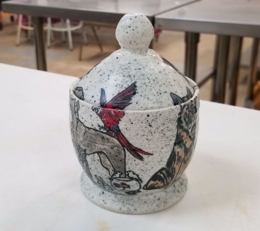
We use Frost for its whiteness but it is finicky. Compressing was key to solving these issues but how it was compressed became critical, especially around handle joints. Here is an old bad video about compressing https://youtu.be/jVNJELUpclk. Once we started being religious about our compression the cracks disappeared. Same for joints, which often we clear glaze, so any crack shows up. Best idea, re-evaluate how things are compressed and whether they are truly denser when you are done. The bowl below is frost, the mug Is frost, just warm lighting, it reveals the type of handle joint which deserves lots of compression at attachment time when it is clear glazed. Hope that helps! Threw in a bisqued version below before spraying the clear glaze. Frost is very white.


-
Peroxide ends up as water so it could thin the slip. If I google oxiclean the ingredients appear to be sodium percarbonate, sodium carbonate, surfactants (detergent) .... polymer ...... water etc.... which decomposes to water and soda ash So the oxiclean could change things a bit. Probably ends up to be more about proportions.
-
I guess I always determine the load so I always try and choose the stacking as appropriate. Seems like I am solely responsible. I never infill a kiln with things that don’t need firing, It does serve a purpose for many though. I will maximize the space available as practical. I just see it as using more electric so I see little value in that unless attempting to simulate a condition.
-
Duncan kiln with funky fiber lid
Bill Kielb replied to Catatonic's topic in Equipment Use and Repair
http://www.ktrefractories.com/hightemp_coating.cfm https://www.ceramaterials.com/fiber-glue-rigidizers/ Suggest: Search refractory coatings rigidizer..- 16 replies
-
- 2
-

-
- old kiln
- fiber insulation
- (and 1 more)
-
Wow, that’s gotta be on the Genesis control then. Good to know.
-
Wow, seems sort of excessively off. So I wonder if similar applies to bisque? Any chance the operating voltage is low by 10%, maybe worn breaker? Just seems a lot for a new kiln.
-
Skutt Envirovent II - is it supposed to be so LOUD?
Bill Kielb replied to kristinanoel's topic in Equipment Use and Repair
Yeah, measured on a two kiln setup, they end up starved. They work, just not able to move near their design air because of the high losses on the suction side. This is fine for their design, since all the production motors are externally cooled just generally not good for a fan that cools itself such as an in-line fan. If you hook up a 100 cfm in-line fan, it will not discharge 100 cfm drawing through a few 1” holes. The dual Orton setup was measured at 14 cfm total discharge on a 100 + cfm rated fan. The inlet size was 3 - 1” holes on each kiln so six 1” holes or about 4.5 square inches. A 4” diameter pipe is about 12.5 square inches so no surprise, a big restriction. In their defense, they don’t need anymore since airflow through the kiln is way less given a 1/4” diameter hole or two into the kiln. They are starved because of the inlet restriction, which is fine for their use and design. Not necessarily for a quiet in-line fan that gets cooling by the air through it though.- 26 replies
-
- 1
-
-
- envirovent
- skutt
- (and 2 more)
-
Skutt Envirovent II - is it supposed to be so LOUD?
Bill Kielb replied to kristinanoel's topic in Equipment Use and Repair
If you swap for an in-line fan and use the same kiln pickup, the existing mixing box is usually very undersized to let the proper amount of air through the fan. In-line fans are self cooled, you could try an in-line fan rated for dryer booster service to deal with the starved condition, but these are often rated in the 200 Cfm rangę, so nosie and overkill become your issues. This type of fan can be enclosed for noise, but it must cool itself with enough exhaust air. When we actually MEASURE the air that can make it through the commercial units its generally on the order of 1/10 th the fan rating. No surprise since the pickup area is usually a fraction of the 4” diameter it would need for full flow.. The mixing manifolds on the commercial units are generally too small and therefore do not allow much room air to enter. This is fine with an externally cooled motor, but an in-line fan needs this to cool itself. Not an issue as long as you pay attention to temperature of the units and folks often find a goof proof easy way to let more room air in. I have seen folks simply install a 4” open T fitting above the kiln and still get enough suction at the kiln connection to perform as originally designed.- 26 replies
-
- 1
-
-
- envirovent
- skutt
- (and 2 more)
-
Skutt Envirovent II - is it supposed to be so LOUD?
Bill Kielb replied to kristinanoel's topic in Equipment Use and Repair
@kristinanoel Just an FYI - this motor has a separate cooling fan built into it (Notice the slots on the rear of the motor) so if you cover this with a box to reduce the noise you will need to let cooling air in and out of the box and motor else this motor will very likely overheat fairly quickly. -
Skutt Envirovent II - is it supposed to be so LOUD?
Bill Kielb replied to kristinanoel's topic in Equipment Use and Repair
It can be done, but the design MUST limit the temperature of the air going through the fan. Here is a simple design that picks up as much air as the original and also draws air from above the kiln, virtually no noise, same draw from the kiln and the blower runs super cool but a lot of care was taken to dilute the kiln air with room air,, plus a goof proof vent above the kiln which ensures there is plenty of “cooler” dilution air. Most of these fans purchased run a bit on the “starved” side meaning if allowed to they would pump more air, just the pickup side is rather small so they often run in a starved fashion. As a result, manufactures specify steel fans that can survive 140 degree air anticipating that folks may or may not install these and set them up particularly well. Starving these fans tends to make them a bit noisier. We measured and designed something to be equal or better than the original. This is not for everyone as making sure the fan stays cool is essential. Can this be done so virtually no noise is created? The answer would be yes with a good deal of design thought, experience and some goof proof way to ensure folks don’t inadvertently block things off and overheat the fan. This design would work nicely for a pickup above the kiln (hood) with a downdraft metered supplement added to it. https://youtu.be/etpa2Pc9Hug -
Nice work, interesting tool. Hats off for providing it. If you look a post or two above there is a trial and error method, sort of a potter friendly way to sneak up on clarity. The young lady that wrote the article freely shares her test findings as well, so your calculator and distribution sparked my memory to share her - test, test, test style solution. Some potters love to calculate, others love to test. Your calculator seems very intriguing IMO. The recipe posted above is not intended to be one of greatest clarity, in fact there is evidence in the recipe that her design intent addressed other issues for her studio clays. Interestingly though, her method does involve finding the best amounts of silica and alumina for,greatest clarity by trial end error if you will.
-
I don’t think her studio clear is the clearest it can be likely for fit reasons, so it will be interesting, but I did think her tests were a nice thing to know and doable for most potters so a practical observation. I really like her, she freely makes her tests available and shares. You may have something pretty cool with the calculator though, so that would be handy as well for serious glazemasters.
-
Great stuff! I always forget sort of a practical potters trick to clarity so I need to make sure to mention it here. A bit less scientific, but a nice practical potters approach, I think to clarity. Anyway done by Sue McCleod and offered free to anyone who is interested in eeking out their best clarity. https://suemcleodceramics.com/getting-clarity-with-clear-glazes/
-
I like it! Backs up the theory that slow is sort of everything for more even firing. As far as more energy it’s still the shell losses and the mass of the kiln so that makes complete sense to me. At lower temps the difference in energy between the elements and everything to be heated is greatest, so that and a relatively fast rate has to be some sort of exponential relationship. Later the elements and wares are closer in temperature while shell loses are close to a linear percentage so easier to maintain a slower rate...... as long as the relays can cycle fast enough. That old ten second minimum was likely there to save relays and also likely helped prevent some overshoot in the early stages but may have caused some undershoot later on made up by longer relay on time. The percentage activation is golden and is a nice indicator of the loading. This process from basically zero to 2000 is tough to tune as it’s changing significantly and loading changes the effect on the zones. Anyone who has spent an afternoon tuning a pid module for something simpler would understand. The lid makes total sense to me and aligns with IR camera stuff we have taken as well. We should take the data and curve fit it ............. why? Geek alarm, never mind. Nice data, thanks again!
-
Those are still really good numbers in my experience. I used to even things out as a last resort by dropping the relay cycle time on the old V6cf to ten seconds so I was curious how much the SSR’s would improve this. Pretty impressive IMO. Thanks for sharing.
-
350f per hour is killer speed for last segment firing rate. Not that you would ever do it, but I find most kilns are lucky to maintain 120 per hour at the very end. Nice kiln!
-
@Pres might be a good time to see what the final segment speed was in the fast and med slow firing. I am guessing it’s in the graphic, could be good knowledge and provide insight. The expected final segment rate for fast fire I believe is 200 degrees per hour, the expected rate for med slow is 120 degrees per hour. Often when that cannot be maintained, things start to overfire as the firing time increases. could be good knowledge to have.
-
I wonder if yours are at +18 and you have the open tubes, so just a construction error. You probably already checked this though........ scratch that thought, that would be opposite your symptoms
-
Geeks only - Raspberry PI controlled kiln
Bill Kielb replied to jbruce's topic in Equipment Use and Repair
Yes that option is available in the column on the left. 60c is pretty common though most kilns should be able to do that. The last 100c of your firing is where most of the heatwork is done so to approximate the heatwork or cone with an electronic controller, follow the chart based on what your kiln can do. When your kiln struggles to make minimum final rate, things will just tend to overfire because of the excess time it takes and it usually means time for new elements. Most kilns require an element change when the elements have grown in resistance by 10 - 15% from their new value. -
Might be worth trying the medium slow. Pretty popular schedule and for larger kilns generally can finish more even and on cone with a pre programmed final segment of 120 degrees per hour. Definitely closer to the Orton specified 108 per hour. With our glazes we could only get away with fast glaze in our little test kiln, all others just didn’t have the power to really maintain the rates so the results and evenness would vary significantly amongst our four other kilns which range from L&L to Paragon to Cone Art. Might be worth a try, still can slow cool as you like.
-
Do you typically fast glaze fire?
-
Geeks only - Raspberry PI controlled kiln
Bill Kielb replied to jbruce's topic in Equipment Use and Repair
Yes, it’s fairly simple actually. Generally glazes and clay contain silica and alumina of which do not melt below about 3000f (1650c) so fluxes are added to get them to melt at a lower temperature often referred to as a eutectic point. Anyway this reaction is more dependent on time and temperature, sort of like baking a cake where the recipe says 200c for 15 minutes. Time is an important element to get it baked correctly. Cones are made of glaze, so when a cone bends a certain amount of work has been done and we are sure it has received the right amount of heat work or has been baked correctly if you will. It sounds complicated, but not really. For controllers to hit the right cone (which ensures the glaze and clay has received the right amount of heatwork) the last 100c of the firing is completed at a certain rate. So in the chart below if I want to fire to cone 6 and my kiln will do 60 c per hour at the end, then I would pick 1222c from the chart, subtract 100c and my final segment would be programmed: 1122c @ 60c per hour until 1222c.. This is the easiest way to approximate a proper amount of heat work with a controller, peak temperature does not really have a bunch of meaning actually. Sort of like baking our cake, just because I hit 200c, it may or may not be finished to perfection. Anyway, it’s easy to do and helps ensure the right amount of heat work has been done which is important to fully bake the clay and glaze. Unlike our cake, soaking at one temperature does not have the same effect, we use final rate in the last 100c to get a specific amount of heatwork. Most kilns struggle to do 100c per hour at high temp, so 60c is usual and in the center column. Also going this moderate speed helps even out the firing through the kiln. @MarkTilles sorry, just got all my rates corrected above, final edit.


