


cadenrank
-
Posts
213 -
Joined
-
Last visited
Content Type
Profiles
Forums
Gallery
Posts posted by cadenrank
-
-
@Bill Kielb and @Hyn Patty Thank you guys for the information.
The adhesive that all of the ceramic supply stores sell that is described to pair with the Skutt gasket is Dow Corning 732, which, according to everything I can find says "cured material stays flexible for continuous use from -76 to 350°F (-60 to 177°C) and up to 400°F (204° C) for intermittent use". Struggling to find any other information in the SDS, not relative to staying flexible, but I haven't found anything else to suggest it's rated to 600.
I see a brand called Imperial that the hardware store sells that is rated for 600°f. I'm sure this one would probably be better for the application, but I'm wondering why most suppliers sell one for the gasket that's only rated for 400.
I'm going to just order a new gasket, I don't think there's any way I'd be able to get all of the silicone off of the one that didn't cure. The plenum cup I think I can get it off of but the fiber gasket probably not. -
So while working on one of my kilns, the fiber gasket that sits between the plenum cup and kiln got damaged. I ordered a new one, and was advised to use any silicone adhesive between the cup and gasket.
All of this went without issue, however, 48 hours later, the silicone has yet to cure at all. I read the tube, says to check expiration if it doesn’t cure, sure enough it’s years expired.
I don’t have any concerns about getting the uncured silicone off of the plenum cup, but not sure how I’m going to get it off of the gasket.
So my problem, do I need to get all of it off the gasket? Both from a curing standpoint for the new silicone and from a firing standpoint (thinking like, uncured silicone getting hot or vaporizing or something from the heat)?
or should I just get a new gasket on the way?
-
1 hour ago, Bill Kielb said:
I personally have seen them fail on the highest loaded elements in the least cooled ares. They are not big enough or have enough surface area to keep the connection cool for the amount of cooling air passing them.
Improving the cooling airflow can help if the convective flow from bottom to top can be improved. Reducing leaks out of the kiln by stuffing with high temp insulation can help for radiant and convective losses as well.This makes sense.
1 hour ago, Bill Kielb said:The simplest solution has been to extend the element pigtail more and position for best convective cooling, just to get some additional cooling to the connection.
conductivity plays a role so copper best, brass next, followed by steel / stainless. An old easy connector to build is drill a brass bolt, use the bolt and two washers. Sandwich the wires between the washers through the drilled hole. Increased convective cooling (heat sink) easy to achieve this way, thermal conductivity less of an issue but surface area as well as mass very important. So this can be done with steel and stainless, just harder to fabricate and not thermally as conductive.
Good to know. I'll see what they have at the store.
7 minutes ago, Mark C. said:How about copper split bolt connectors . Electricians like me use them on all large wire connec tons as they are made for large amp draws. They are usually all copper and a brass nut. They are spendy and come in a variety of sizes. Also I use copper coat on these connections as that keeps out all corrosion. Never had one fail.
I never thought of a split bolt. I'll see what I can find!
Thank you everyone, again, for the help! -
I really liked the one's pictured (they're from TheCeramicShop, who say's "They are made of zinc coated copper for higher resistance to corrosion, and longer connection life"). Price was good, and I was confident in the connections when I made it, but the amount of times these have failed now have made me weary of them in general. I believe I did put the element on top in them, but not certain. And each time I've had a burnout (4 of them now) I've tightened all of the others while I had the box off. I just feel the washers bolt and nut is much more secure in combination with crimped on ring terminals on the wires, while still being able to take them off easily during changes or other maintenance. I never had any issues with corrosion or burn outs on them or getting them off when they needed to come off.
24 minutes ago, neilestrick said:Use stainless steel, put a washer on each side, use a lock washer, and connect the feeder wire to it with a high temp ring terminal. Totally old school and very good. I'd use a 10-24 bolt.
Thanks for the information! I figured stainless hardware would be fine, but wanted to double check before I went and bought some. I think this is the route I'm going to go.
-
Hello all!
Today, I got the 8 awg cable that supplies my one kiln upgraded to a 6 awg cable. The intention of this is to upgrade my elements to a different resistance configuration that will both supply the kiln with more power and hopefully more even heating, as well as make replacing elements easier (as I won't need to get them custom made, and hopefully won't have to do any stretching of elements, discussion of this project for this kiln has happened in the past on another topic of mine here, but about time for new elements, so progress towards getting the circuit ready for that transition is underway)
This kiln currently pulls around 30 amps (8 sided, 5 brick layers deep. Skutt 822 is the most similar model.). At the end of this project, it should pull roughly 34.7 amps, with the new elements on the 6 gauge copper, and a 50 amp breaker circuit that's now finished for this kiln.
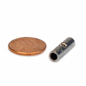
During my last element change I used some of these types of connectors:

I like these connectors because of how easy they are to connect, and they allow for changes to happen and repairs to happen much more easily than the crimp on connectors. My issue with these is that over the life span of these elements, I've had 4 of the 10 fail. They corroded, and eventually burnt out at the connector, leaving them unusable because the wire had melted where it burned out and essentially welded the connector to the element tail.
This kiln is an older model kiln with entirely new components and wiring. The kiln originally came with brass nuts, bolts and washers as element connectors which I wasn't a big fan of at first, however, of all the types I've tried (the ones pictured, Skutt's crimp on barrels, and Paragon's version (which I mostly don't like because of cost)), I think the nut and bolt connector is the one that I like, and feel the most comfortable with. All of the connectors like the ones pictured above that have burned out I replaced with the old original brass nut and bolt and washers that I saved, and they still look perfect and feel the most secure to me while being relatively easy to perform repairs or replacements with in the future.So that being said, my question comes down to material. I don't have enough of the original brass nuts and washers to do the whole kiln with them once the new elements go in, so I'll need to purchase more and I'm just wondering what size as far as bolt goes, material they're made of, etc. Is brass the best option? Stainless? Are the brass nuts/bolts/washers I'd find in big box hardware store good to handle the heat and voltage/amperage that will be passing through it? Any other recommendations on where to get some that would if not?
Thanks as always for any information and any help!
-Caden -
Firing went smoothly. Periodic peeks at that connection didn't show any heat or anything.
The only thing I didn't like about it was having to make the loops in the element pigtail. But, I remember always feeling confident that it was tight once it was done. I believe they are brass hardware original with the kiln, and I saved them (which is what I used in this case) before I switched over to the screw type terminals. I like those too, but the bolt and washers just feels so much more secured. -
Done. Kiln is running. Gonna keep a close eye on it, but pulling normal amperage again, resistance measurement was the same as the other elements. The ring terminal to ring terminal and bolt connection feels more secure to me than most other connector type connections I've seen. Makes me want to think about going back to the element loop and bolt/washers and ring terminal design the kiln originally had when I got it. I never had any second guesses about security with that type.
-
@neilestrickI cleaned it up with some emory earlier. Will try the ring terminals and a bolt. Just needs to last until I replace elements.
Thanks again everyone. Will update how it goes. -
I like the screw type connectors too. All of the others in this kiln are fine, but this one is definitely not reusable. The Euclid one's are high on my list for replacements for next element change. I was hoping to find a solution that I had on hand to make the repair to fire today.
I appreciate your offer, though. I have enough to fit into the barrel connector I have, as well as plenty to fit into another type of screw connector, I just can't crimp the barrel connector because the type I have won't crimp within the space I have, and I don't have any spare screw type connectors on hand.
Wow, glad to hear you haven't had any major damage so far! Stay safe. -
10 minutes ago, neilestrick said:
Can you post a picture of the connection? That will help us see exactly what we have to work with.
You mean just the element side? It's just about less than a quarter of an inch outside the insulator. I have extra feeder wire. The burnt out connector is one of these types:

And unfortunately I don't have any extras. And the burnt out one is heavily discolored, and full of some welded wire in the bottom of it now. The element pigtail itself still looks fine, just the connector and end of that feeder wire were toast.
I can crimp a ring terminal on the element and make a good connection, with a ring terminal on the feeder as well, then a nut, bolt and washers to connect the two. I'm just not sure if the ring terminal on the element pigtail (900f rated, for reference) is a good option or not.These are the only terminals I do have excess of, but that little bump of metal in the middle makes it so I can't crimp my crimping tool onto it with the element inside of it. It won't let me get close enough to the kiln to crimp it down right, and crimp it down on the element too.
also I just hate this type of connector. I probably only have a month or two of firings left on these elements anyways, but just trying to make them last. -
Yesterday when I went to start a glaze firing, I was greeted with a nice little firework show from inside the control box of my kiln. I stopped the kiln, and identified a connector that was heavily corroded, and the remaining feeder wire basically welded inside the connector, and the wire itself broken off, free to arc to the jacket.
I have some spare crimp on connectors, but these connectors have a small piece of metal in the middle, which only allows you to crimp past a certain length from the middle on each ends. (Which is why I never used these in the original install). I don't have enough element length left to crimp this style of connector on.
A thought I had was to use a high temp ring terminal (900f rated) crimped onto the element, then crimped onto the wire, then use a screw, nut and washers to smash them together, but I'm not sure how good of an idea this is. My idea is that people use the ring connectors at that point too, but not attached directly to the element so I'm curious if this would work.
I need to replace elements soon anyways, but the thought of crimping it (or anything) and then it not working or lasting until then pretty much leaves no ability to replace without cutting all of the remaining element off.
I tried to use the screw, nut and washers to sandwich onto the end of the element like it was when I got the kiln, but there isn't enough to hold securely, and there's definitely not enough to make a loop.
I know it'd be better to wait until I can get a new one of my preferred connector (the screw down types), but unfortunately that's not a fast process.
Any ideas? -
7 minutes ago, Bill Kielb said:
The Skutt kiln sizing in the manual seems fine.

This isn't what skutts distributors, or their main website/product page for this kiln shows.
In fact, I can't find a single product, technical, or kiln specific pdf from Skutt other than the one in your photo that shows 6awg for 822 -
28 minutes ago, Dick White said:
I don't know why Skutt lists it that way. Skutt also does not list the breaker size, only the wire size and the plug configuration.
Two of their distributors list 50 amp breaker in their specifications for the product. I thought that google information was from Skutt, but still. Giving the amperage, and the wire gauge still leaves questions following the 125% rule.
41 minutes ago, Rockhopper said:The reasoning is simple: If the wire is rated lower than the amperage that the breaker will allow to pass through it, the wire itself becomes the 'fuse', and could get dangerously hot without tripping the breaker. (You can use a heavier wire than required by the breaker, but not lighter - so 12ga on a 15amp breaker, or 6ga on a 40amp breaker is OK - but 14ga on a 20amp, or 8ga wire on a 50amp breaker would not be allowed).
This makes sense to me. I just never really thought about the conductor needing the 125% increase too until I was reading Skutt's recommendations for references for this kiln. That being said, I also didn't think on it very long. Logic eventually would have told me that lower rated wires can't be used on higher rated circuits. But, then I started to question if maybe my memory on 8 gauge NM cable's specs were wrong -
53 minutes ago, neilestrick said:
regardless of which type wire you use, which means that for 50 amps you need 6 gauge wire.
You're referring to the circuit rating that the breaker would cover, when you say 50 amps? As in, even if the kiln wouldn't pull that? I understand the >125% <150% rule, but am just verifying that it does or does not apply to the conductor as well. I wish I would have run 6 gauge when I originally did the project like I did with my other kiln, but originally this kiln only pulled 24 amps, so I never thought I'd need the extra amperage there.
Anyways, I plan to keep this kiln near 30 amps, I mostly just thought it was odd that skutt recommended 8awg and a 50 amp breaker for that specific model of kiln -
So, I don't have this kiln, but I have a kiln pretty much identical to it in size, and make up. I've been doing some calculations relative to putting new elements in this kiln, to get a more even, but still a nicely powered kiln, maintaining a safe amperage draw on the 40 amp, 8 gauge circuit that my kiln currently uses (at 30 amps currently). I think I have this part of a 30 amp, balanced (top and bottom elements hotter) configuration, covered, but have noticed something when looking at Skutt's 822 specs.
Skutt says recommended wire size is 8awg, and amperage pulled is 33.4 amps. and recommended breaker size is 50amps for their 822 model kiln.
From my understanding, isn't 8 gauge wire not ideal to be on a 50 amp circuit? Even though the kiln isn't pulling 40 amps, I always assumed the 125% of rated load rule also applied to the conductors feeding the kiln, as well as the breaker.
So my question here is, if this specification is not outside of best practices, could I theoretically use Skutt's element design in a kiln matching that size, on the existing circuit that I have, just by increasing the breaker size and not increasing the conductor size? The kiln itself's wires are all able to handle that added amperage, and the receptacle is already a 50amp receptacle, but I'm just curious what the groups thoughts on skutt's specs for this kiln are.
After googling the 8 gauge wire information, I suppose it comes down to the type? I'm seeing the NM Romex type of 8/3 (which is what is run to my kiln) seems like it's max amperage is 40amps, but thhn seems to be rated for 55. Still curious on thoughts here. -
6 minutes ago, neilestrick said:
Testing the SSR directly while under load is darn near impossible in a Skutt, and ceratinly wouldn't be safe with the insulating baffle loose. But you can test it at the terminal strip on the element side of the baffle, you'll just be a few inches down wire from the relay itself.
I'm not sure I follow the last portion of this. How would the access be there to probe with the baffle in place on the element side?
7 minutes ago, neilestrick said:Is this is the same transformer it has always had, or did you swap it out during all this troubleshooting? I wouldn't expect a transformer to suddenly start being the problem unless it actually died, which is really rare. The 16.5 volts was at the relay, correct? Do we know what the voltage is at the transformer output/control board input? Sorry if you posted that already, I couldn't find it. If the control board input is normal (24V) but the output is high (16.5V) then that would point to a control board issue, which could also explain a lot of the other issues.
This is the same transformer it's always had. Didn't decide test it until the kiln killed another relay. 16.5 volts on the output of the controller to the relays, and the transformer is producing 30 volts AC across the outside terminals of the output side. 15 from center tap to either outer posts. 242 volts input at the transformer.
-
1 minute ago, PeterH said:
That confuses me too. IIRC you measured 243V in and 16.5v from one arm of the output.

The red, green, and yellow markings on this diagram aren't the transformer, that's the mechanical relay. I didn't measure the transformer last time. Those values are still accurate (240-243v inputs)
-
3 minutes ago, Bill Kielb said:
The transformer is a pretty passive device with a fixed ratio of windings. More likely the input voltage is high, so then why? That goes to does it measure the same as the mains voltage, does the home have an open neutral, etc….. from there if still really high a call to the utility company as you should be limited to 240 vac +/- 10% I believe.
Input voltage was 242v.
I'll have her doublecheck all the thermocouple points as well. -
Just now, Bill Kielb said:
Seems high to me especially if from a regulated circuit but your SSR functions 3-32 volts so not likely to make the SSR stick on.
Yeah I don't think that voltage is the SSR's issue, but may be contributing towards the mechanical relay premature (3 firings) deaths.
The transformer's data sheet said output should be 24 v, with 12 from center post to each outer post. Which isn't what it's producing. -
In regards to testing the SSR while it's operating, that's not an impossible task with how quickly she says it happens, just would be difficult to be in there, and also have elements connected to produce the error and to have a load on it. But I'll start with A. verifying the issue still exists, because we didn't find any source of continued, or otherwise uncontrolled voltage. B. trying different programs. Then if all of that is normal findings, go with C. try to figure out how to test the SSR during the failure.
-
I will look further into the programming.
What's everyone's thoughts on that transformer voltage? I know we discussed that 16.5 on the control side of the relays was technically high. But it seems excessive that it would be causing this many repeated relay deaths in this short of time. We don't know that the relay burn out issue is still an issue after wire replacements though. Just presuming it may still be present. -
19 minutes ago, neilestrick said:
Interesting. We see quick error like that that on multi zone kilns if the relays and thermocouples aren't set together properly, like if the zone 1 TC is paired with the zone 2 relay. But on a single zone it would only happen if the TC system is backwards or it's not getting any power.
The other option, would be a relay stuck closed, or a controller commanding power output improperly. This was Skutt's diagnosis. but both of those do not appear to be happening in this case from testing. I believe she said the error happens in less than 20 minutes. But possibly said it was happening even faster, and when the program stopped, temp does stop rising, and there's no output when the kiln is not in a program.
19 minutes ago, neilestrick said:Just to rule out any programming issues, what firing program is she using when this happens? It could be that if she's putting in a rate of 500F/hr or something very fast like that, that the kiln simply can't keep up with the traveling set point at the start of the firing since it takes a little time for things to get hot. Does it happen with a rate of 9999? At 9999 the controller doesn't follow a traveling set point, it just goes as fast as it can and is happy with whatever speed that is.
I will look further into the programming. I'm unsure of what she was using.
-
3 minutes ago, neilestrick said:
If it errors very quickly, it's usually because it's not getting any power at all, or something along the thermocouple system is installed backwards and as the temp in the kiln rises the controller reads it as going down and it reaches the 50 degrees difference very quickly.
This would make more sense given my testing, however she said that the temp on the 7segment display is rising when this is happening.
-
1 minute ago, neilestrick said:
How hot is it getting before it errors? Also double check that the controller is set for one thermocouple.
From my understand, within a couple minutes of starting a program.
This kiln uses Skutt's 3-Key controller, and I don't believe there's any user configurable options to change the number of thermocouples.


Kiln vent gasket adhesive
in Equipment Use and Repair
Posted · Edited by cadenrank
As always, and again, thank you everyone for the responses.
@neilestrick I was thinking about trying it. This last maintenance project has taken this kiln out of service since New Year's (mostly just waiting for parts), so the thought of just firing it and just keeping an eye on it and seeing what happened after crossed my mind, but I already had got the old one off, and got the plenum cup clean. I could still put the old one back on (It still has the uncured silicone all over it) but I already ordered a new gasket. I might put it back on just to bisque while I'm waiting for the new one and then clean the plenum cup again later if it doesn't cure still after firing.
@Rae Reich I saw that when I was googling it. I found a JB Weld 100% Red silicone one that's rated for 650 that's available at an auto parts store nearby, so I'm probably going to go that route when the new one comes.