


Pieter Mostert
-
Posts
281 -
Joined
-
Last visited
Content Type
Profiles
Forums
Gallery
Posts posted by Pieter Mostert
-
-
@Joseph F When I increased the phosphorus in my original glaze (see link in my reply to curt) there was a more abrupt transition between the orange centre and the background colour. (The application on this tile was way too thick, but you get the picture)

I think you'd have a similar result if you increased the phosphorus in #9.
@High Bridge Pottery Yes, alumina increases up and iron to the right. If the glazes in my grid behave similarly to the ones in the paper I mentioned, then for a given column, the ones lower down start softening at the same time as the ones higher up, but they're more fluid at the top temperature, so the rate at which the viscosity changes with temperature is greater. I think this sudden stiffening of the glaze as it cools is trapping the bubbles.
After looking at the paper again, I realised that the conclusion I quoted was for clear glazes only (so alumina can't be too high, as in the glazes I tested). Even here, the data isn't totally convincing.
-
Sorry for not responding sooner; I've had internet trouble at home over the weekend.
@Marcia Selsor Funny, I was looking at that paper on crystalline glazes yesterday. I know that the knowledge of crystalline glazes has advanced alot since then, but it's still a great source of data.
I think Ferro 3191 is reasonably similar to the frit I was using, but I'd have to import it. Will try some local options first.
@glazenerd I've noticed that in general, my tests on the red earthenware are more likely to pinhole than the ones on white stoneware, so that could well be the result of iron sulphide. But in this case I think the source of most of the gas and subsequent bubbling is from the decomposition of Fe2O3 to FeO. I can't explain why it would happen at 1130C instead of 1230C, which is the usual temperature given, but it still seems to me to be the most likely explanation.
@curt The oxides other than iron and alumina are the same as in this recipe. The left-hand column has 5 - 6 % red iron oxide, which translates to 0.09UMF.
The reason I think the bubbles may still be forming (or at least expanding and bursting) as the kiln cools, is that the later ones sometimes have different colour developing. For example, in the first close-up, the squashed bubble in the centre is more orange than the two adjacent to it, which must have formed later. This is assuming that the crystals giving the orange colour only form at lower temperatures.
I may be (probably am) completely wrong about the effect of changing viscosity on the bubbles. I guess I was thinking something along the lines of what Tony Hansen talks about here:
Quote- Step 4: Use this step if you need to heal blisters. Free-fall 100F and hold. The reason: The lower temperature imposes the melt viscosity sufficiently to overcome melt surface tension and burst the bubbles but still affords enough fluidity to heal them.
I really need to go back and read the bubble thread again.
-
Here's what I think may be happening with the bottom left corner.
There's a 1914 BSc thesis by Sidney Sewell where he measures the viscosity of a family of glazes as a function of temperature. All glazes have 0.3 K2O, 0.7 CaO with Al2O3 ranging from 0.3 to 1 and SiO2 from 1.8 to 6 UMF. (Well, that was the plan, but the little slacker didn't finish testing all of them in time). He found that for fixed SiO2, decreasing Al2O3 increases the rate at which viscosity changes with temperature. So assuming this is also true for the family of glazes in my grid, as the kiln cools, the ones near the bottom increase in viscosity more rapidly than the ones near the top. So if there's a window of viscosities in which the glaze is too stiff to allow bubbles to grow, but fluid enough to heal over burst bubbles, the low alumina glazes may not be spending enough time in that window.
Of course, this doesn't explain why adding iron makes the bubbles heal over. Maybe in this situation it's acting like alumina?
I'd be interested in hearing any other explanations.
-
Here are the results of a Currie-type grid where I again varied iron and alumina. The proportions of everything else are fixed, and the same as my previous test, except that silica is now at 2.48 UMF (previously it was between 2.12 and 2.27). Based on the results of the first test, I reduced the range of iron slightly, to run from 0.09 to 0.22 UMF from left to right (previously 0.07 to 0.22). Alumina goes from 0.22 to 0.34 from bottom to top (previously 0.32 to 0.46)
Below is a screenshot from Glazy showing the corner glazes (with Fe2O3 not regarded as a flux). The ones circled in red are my first test, and the ones circled in blue are the second.

I kept essentially the same firing cycle (slow firing to 1132C, with a 45 min hold at 950C on the way down. Cone 4 buckled but not flat on the shelf the tiles were on). However this time I fired the white stoneware above the red earthenware tile. This time I also made a little hole in the glaze in each square (based on Curt's suggestion of scoring a 6 o'clock line), but I can't see any evidence of them.
On red earthenware:
On white stoneware:

As in the first test, the tiles get progressively darker as you move from the bottom left to the top right corner.Unlike the first test, which had unhealed bubbles around the top right corner, here the bottom left corner had the most unhealed bubbles, which I don't know how to explain. The sort of stringy, collapsed bubble thing reminds me of another series of iron glazes I'm working on which are also relatively low in alumina, and form ugly blisters when thick. I'd have thought lower alumina would mean lower viscosity, and therefore give the glaze a better chance of healing over. While I was writing this, I thought of a possible explanation, but I'll put it in a separate post.
The orange background appears with similar levels of Al2O3 for both tests. It would be interesting to do a grid varying silica and alumina around these points to see how far this region extends.
I love the variety of colours and combinations of colours that this tile produced. It's hard to pick a favourite. The area in the middle is the most striking (and is what got me started on this series of tests), but I'm also drawn to the yellow-purpley combination in bottom right corner. In fact, if you look closely, the purpley background has tiny areas of red, which might be encouraged by changing the cooling cycle.

The top left glaze and the one to the right of it (#1 and 2) are really interesting, even though I'm not mad about the dirty yellowish - orangey background. I'm intrigued by the blue though, and will probably play with the amount of phosphorus to see how it effects this.

But the glaze I keep coming back to is the third from the top in the left-hand column (#11). I really love the subtle blue halos.

Unfortunately the frit I used for these tests has been discontinued, and the replacement my supplier claims is the same is slightly different. Time to buy a big batch of frit from a supplier that provides the composition, if only I can find one.
-
Well, on Glazy you can specify the firing type and type of surface, although not everyone does this. I agree that the other variables are important, and should be included if the goal is for other people to replicate your glaze. On the other hand, I think of recipes I find online as starting points for tests, since most of the time I have to (a) tweak them to work at cone 4 instead of 6, and (b) reformulate them in terms of the ingredients I have available. Also, I'm limited by how fast and how high I can fire, so even if someone gave a firing schedule for cone 4, I might not be able to follow it.
Back to Currie grids: I did another grid not that long ago which I'm really happy about. I'll post pictures once I have time to pull my thoughts together. In the same firing I tried out a couple of glazes from my first grid. The photos below are of the one in the middle of the bottom row (tile 33):


The one on white stoneware went on thicker, and ran, as you can see. The one on red stoneware has fewer pinholes (not sure if that's due to thickness or claybody), but the spots are smaller. If there's one thing I've learnt from these tests, it's that I need to use more glaze and a bigger container to dip in. I had planned to dip in and out slowly to ensure that the top of the bud vases had a thicker application, but I was too busy trying to fit them into the container to do that.
The other oilspot type glazes I tried were less successful.
PS: Happy Thanksgiving, for those of you who celebrate it.
-
I'm going to have to start ditching my test tiles at some point too. I don't fire that often, but they're already staring to clutter up my studio. I'm just a bit wary of relying on photos, since there are some aspects of glazes that are hard to capture in a photo.
I use Glazy for recording most of my tests, but a system that naturally caters for recording things like application thickness and firing cycles would be ideal. I know that Derek Au, the creator of Glazy, has thought about this, but at the moment he's busy rewriting the current version, so I don't think it'll happen any time soon. The new version of Glazy will be open-source, though, so if you're up for doing it yourself, this would be a good place to start.
-
On 20/11/2017 at 4:18 AM, Joseph F said:
Now that I have a slab roller and I can roll a slab to the same thickness every time it means I can create uniform test tiles that are the same thickness as well. So I roll out a slab, put ruler over it and cut out a bunch of rectangles that are flat. Then I will just roll a slab of clay take a tool(made from the slab size I want) and make 7 trenches that are the same width as the tiles that I am using.
Something like this:

Then when I do a currie test I will have 2 tiles side by side, and 35 test tiles that are just rectangles. I will mix the cup with milk frothier, syringe the glaze into the square, then dip the tile into the cup and then place it into the trench on the other tile in the same place as the grid. Thus if any glaze runs or what ever it will be contained. This is a really fast way for me to get the all the information in a single firing!
I think this is a good direction to follow. For my regular test tiles I've been using something similar, except that instead of trenches I just have one or two supports on which I can lean the test tile. The supports are in the shape of triangles pointing upwards, if that makes sense. I put a layer a kiln wash over the support, so minor glaze runs don't ruin it. It could do with some improvement though, since my prototypes are pretty crude, and sometimes the tiles stick together.
Anyway, for vertical tiles for a Currie grid, you could make 7 slabs, each with a row of 5 rectangle-shaped depressions, like the squares in a Currie grid, into which you could pour the individual glaze tests at the same time that you fill the corresponding squares in the regular grid. This way it'll be easier to keep the tests in the same order as the regular grid, and you won't have to dip them. A potential problem is that the very runny glazes will have a puddle of glaze attached to the bottom, assuming you can remove them from the support, which will make stacking them for storage difficult. But you could just omit the ones around corner C.
Actually, it might be better to have 5 slabs with 7 depressions each, otherwise when you put the slabs together flat, the height of the whole thing will be much greater than the width.
-
Please keep the tiles coming.
The quote from Tom Turner that Min shared seems to contradict my suggestion that reduction makes copper a more powerful flux. The only explanation I can think of is that perhaps with the finer mesh sizes of SiC, all the SiC is reduced earlier in the firing, so there's some re-oxidation happening.
- Min and Joseph Fireborn
-
 2
2
-
Reduction makes iron a more powerful flux, so if the same is true for copper, that would explain why the SiC tiles appear more fluxed. But I don't know if this is the case.
-
4 hours ago, Joseph F said:
On a different note, someone just updated Ian Currie's website and it's terrible. The calculator page is horrible. Looks like I am going to be remaking that in google spreadsheets soon. Yuck.
There's a nicer online Currie grid calculator here, made by Tom Demeranville. The only downside is you're restricted to 4 fluxes.
-
Clara Giorello has done a lot of testing with SiC copper reds. If you're on Facebook, it may be worth joining the Ceramic Recipes group, since SiC glazes come up from time to time.
-
Curt, I don't see any reason why you couldn't get oilspots the way you suggest. If you fired in oxidation up to the point where the glaze was melted enough to hold bubbles and then reduced, you'd be reproducing the thermal reduction of Fe2O3 (I think...). However, I suspect you'd be limited in how much higher you could fire before the spots dissolved back into the glaze.
Concerning the boron, it's worth keeping in mind that on the old thread of mine you mentioned, Neil posted a cone 6 oilspot recipe which only has 0.024 B2O3 (UMF). In my Currie grid, B2O3 is 0.09, which is still on the low side for cone 4, although the other families of spotty glazes I'm working on are higher at 0.32, 0.33 and 0.38. Not sure what to make of that.
Joseph, I've started making a bunch of small bud vases to test glazes on, like you do. For most of my pottery life I've been more interested in form than glazes, so now I'm in the unusual position of having to decide on pots for my glazes, rather than glazes for my pots (although I've been using terra sigillata for my large coiled pieces for a while now). I think oilspot glazes really suit the shape of Jian tea bowls, but I'd need to get myself a wheel if I wanted to do something like that.
-
It could be, but I'm a little hesitant to draw conclusions about glazes based on phase diagrams.
-
Thanks LT! I'm looking forward to going through those notes.
Joseph, it's a mystery to me why I'm getting the spots, since I fire really low and slow to get to cone 4. My max temp was 1129 C, whereas the iron bubbling in traditional oilspots is only supposed to start at about 1230 C (depending who you ask). The major difference is that my glazes have boron, so that might somehow be catalysing the process, or it could be some other process happening. But the fact that glazes like the ones I'm getting are quite rare at mid-fire temps, seems to indicate that there's something about the way I fire that makes a difference. I've seen papers that mention high iron boro-silicate glasses are prone to phase-separation, but until I brush up on the necessary chemistry, I can't say if this is relevant.
-
Joseph, that's good to know, although ideally I'd like all the bubbles to heal in the first firing. Someone's mentioned holding the temperature on the way down to allow the holes to smooth other, but I only held at 960 C in this firing to try get some iron reds, which is probably too low for the oilspots. I know you slow down the cooling, but is this only after first dropping quickly from the top temp, or do you go slow all the way down?
The glaze this grid was based on shows the effect of different thicknesses: https://glazy.org/recipes/8010
I dipped these 4 times, each time covering less of the tile, so that thickness increases from left to right. Here's my theory why thicker glaze layers produce larger bubbles: Microscopic bubbles join up with each other to form larger and larger bubbles, until the bubbles extend beyond the surface of the glaze, at which point they burst. The thicker the glaze, the larger the maximum radius of a bubble that can fit inside the glaze layer, and thus the larger the maximum spot you get.
Curt, I'll have to get hold of a copy of Hamer and Hamer. For this test, I think the striding man may have obscured what was happening with the spots, but I can see how using it and the 6 o'clock mark would be useful in general, especially if the glazes aren't applied as thick as they were here. Looking forward to your next oilspot test.
-
Curt was asking about what appeared to be "counterintuitive to me because I see iron as a flux".
I suggest looking at the non-bridging oxygens per tetrahedron for the melt (I haven't done the calculations) for each tile. It could be that the iron is allowing the aluminum to become a network former by charge balancing. The Fe to Al atomic ratio may also be an informative variable.
LT
I'm afraid my knowledge of glass and glazes doesn't expend that far. Do you have a reference where I can read up on this?
-
High Bridge, I'm fairly certain that the spots are due to bubbles bursting. This paper illustrates how bubbles form spots in traditional oilspots (see figure 1). That said, I'm not sure if the bubbles in my glazes are because of the thermal decomposition of iron, given that I fire 100 C lower than the temperature at which this is supposed to happen.
-
Thanks for your comments, Curt. To answer your questions, what I'm calling earthenware clay is sold as 'Smooth Red Earthenware', but I've fired large coil pots made from it to cone 4 without any sign of overfiring. I'm not sure what cone the stoneware is designed to be fired at, but cone 10 would be a good guess (unfortunately my supplier gives temperatures instead of cones, if they give any info at all). Both tiles were fired to a bit above cone 4, so the stoneware one is definitely underfired. I'm in the process of formulating some clay bodies that are vitrified at cone 4, which I hope to use these glazes on, and while I really should be testing the glazes on these clay bodies, at least I can get an idea of how things change when you vary alumina and iron (among other variables I've looked at) and then apply that knowledge once I've settled on a clay body.
Because I used the wrong kaolin, the glaze I have on Glazy doesn't correspond to any of the ones on the grid. The closest one, both visually and in terms of the oxide composition, is tile 33, but this has SiO2 2.27 and Al2O3 0.33, as opposed to SiO2 2.48 and Al2O3 0.28 for the one on Glazy. Of course, that's assuming the info in the spec sheets is correct.
Iron is increasing across each row, so as a percentage of the glaze, everything else is decreasing. If you include iron as a flux, this would mean all the other oxides in the UMF are decreasing, although their ratios remain constant. Iron can definitely act as a flux in oxidation, as this series of test bars shows:

Here I just added increasing amount of red iron oxide to a recipe that had the same UMF as Seger's original cone 4 composition. What makes things tricky is that you'll get different numbers of molecules of Fe2O3, Fe3O4 and FeO from the same weight of iron oxide, and since there's probably a mix of these oxides in the glaze, how do you convert from weight to UMF?
Regarding iron making the glaze more viscous, I think that this is similar to adding more and more calcium or magnesium to a glaze; at some point the fluxing action will stop and the glaze will become more refractory. I've noticed that excessive iron will make a glaze crawl, although that may also be because of its effect on the glazy slurry, not just the surface tension.
I agree that the surface tension is highest in the top right corner. For the unhealed bubbles, I think high viscosity must be playing a role, since I'd expect a high surface tension to smooth out any dimples in the surface.
You may be onto something with the white tile contributing more alumina to the glaze. If you moved the tiles in the white grid up one or two rows you'd get a better match with the red grid, although they'd still be slightly darker, so that can't be the whole story. If the glazes on the red tile are getting iron and fluxes from the body, I'd expect them to be darker, particularly since alkalies reduce the solubility of iron, according to Currie's experiment Fe4 on pg 161 and 162 of Stoneware Glazes.
There is some variation in the sizes and densities of the spots, though not nearly as large as in your oilspot grid. I suspect that the oxide composition of the cells in your grids vary more than in mine , but even taking that into account, my spots seem quite persistent. I'm working on the theory that the reason I'm getting spots has to do with firing very slowly as I approach the peak temperature. So far I have 4 families of spotty glazes; besides this one, there's the one I posted about in this thread, which has now morphed into this, one with multicoloured spots:

and this one. So either my kiln god has a spot fetish, or there's something unique about how I fire.
-
By the way, the electronic version of Ian Currie's 'Stoneware Glaze - A Systematic Approach' which he published on his website under a creative commons licence, can be downloaded here.
The chapter on high iron glazes confirms my observation about the effect of alumina.
-
The more grids the better
 I can't see it anywhere but is alumina decreasing up the tile or increasing? Looks darker at the bottom to me so that should mean most alumina there. The top right glaze would then be most fluid and probably passing most of the bubbles, a little less silica too. The ones below the arc are not even getting their bubbles to the surface.
If the alumina goes the other way then that ruins my theory.
I have lost many a post so always ctrl+c it all before posting just in case it dies on me.
Oops, I see I didn't say which direction alumina is increasing. It increases as you go up, so there goes your theory
 . If you look carefully, you'll see that all the tiles below the arc, except the left hand column, have spots, so they're definitely passing bubbles. I would guess that the most fluid tile is either the 2nd or 3rd one of the bottom row, since increasing additions of iron first increase the melt, and then begin to stiffen it when it gets overloaded.
 -
That almost happened to me too when I tried to preview my post, but luckily my browser had saved what I'd written.
-
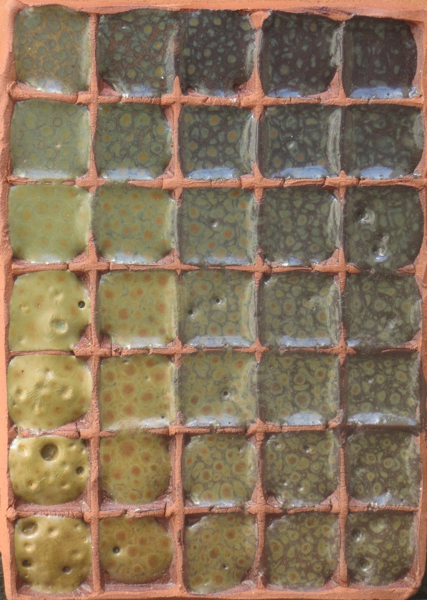
I finally got round to using a couple of Currie grids in my last firing. I varied alumina and iron instead of adding kaolin and silica, so I hope no-one minds me posting in this thread. The tiles are on a red earthenware and a white stoneware.
For some reason I've stumbled on a number of spotty glazes, firing to cone 4. One of these is 'Harris/Giorello 7', which is my attempted reformulation of one of Clara Giorello's variations on Cathy Harris' iron red glaze.Red earthenware:
 White stoneware:
 Detail on red earthenware:
I'd previously tried to vary iron and alumina individually, but miscalculated the amount of iron oxide in the first case, and used a less pure iron oxide in the second, so wanted to do a proper test where I varied both. So I formulated the corner glazes so that the rows have constant Al2O3 UMF values, the columns have constant Fe2O3 UMF values, and everything else is the same. Well, that was the plan... except that I used the wrong kaolin, which resulted in silica decreasing from about 2.27 to 2.12 as you move up the rows (all values are UMF). Al2O3 goes from about 0.33 to 0.46 (EDIT: bottom to top), Fe2O3 from 0.07 to 0.22, and the fluxes and boron remain approximately constant. In terms of percentages, red iron oxide goes from about 4% to 12%.
Some observations.- Increasing alumina darkens the glaze. I've seen this in other tests as well. I'm interpreting this to mean that alumina decreases the solubility of iron in the glaze.
- There's an arc of unhealed bubbles that curves up and to the left. Beyond the arc, around the top right corner, the glaze is smooth. I don't know if this is because the glaze was too viscous for the bubbles to expand, or if they didn't form at all.
- The arc is closer to the bottom left corner on the white grid. I think this is because it was resting directly on the bottom shelf, while the red grid was supported on a plate setter above it, so presumably received more heat-work. This suggests that firing higher may result in the unhealed bubbles smoothing over. But I could be wrong, and I'd be interested in any other explanations anyone has.
- The left-hand column looks underfired. It's also higher than the column next to it, so I'm guessing it has more bubbles trapped inside.
- You can't really tell this from the photo, but the glazes that have spots all have a matte background, with the spots being relatively glossy in comparison.
-
A simpler way to work out how much base remains after removing 2ml from 48ml is to multiply by 46/48 = 0.95833...
So if you started with 30.64g per cup, you'd have 30.64g x (46/48) = 29.23g of the base left after removing 2ml.
At the next step you'd have 29.23g x (46/48) = 30.64g x (46/48) x (46/48) = 30.64g x (46/48)^2 = 28.14g of the base left.
If you continue in this way, you'll find the amounts differ slightly from the ones in the spreadsheet. The difference isn't large enough to make a practical difference, but for anyone worrying about where it comes from, it seems to be due to the fact that when you work out the amount of oxide removed, the spreadsheet takes the proportion of oxide in the mixture to be 0.02, whereas it's actually 0.02/1.02.
-
I'm asking about tiles 11 and 12. In the top photo, these two cells have a lighter, wrinkled strip along the top.


Electric Reduction Firing
in Equipment Use and Repair
Posted
I'd love to hear what you learned. It's unlikely I'll have the opportunity to build a reduction electric kiln in the near future, but I'm still interested.